


A power supply is an electrical device that converts the electric current that comes from a power source to the voltage value necessary for powering a load, like a motor or an electronic device.
There are two main designs for power supplies: a linear power supply and a switching power supply.
Linear power supply: it uses a transformer to step down the input voltage. Then the voltage is rectified and turned into a direct current voltage, which is then filtered to improve the waveform quality. Linear power supplies use linear regulators to maintain a constant voltage at the output. These linear regulators dissipate any extra energy in the form of heat.
Switching power supply: it is a newer methodology developed to solve many of the problems associated with linear power supply design, including transformer size and voltage regulation. In switching power supply designs, the input voltage is no longer reduced; instead, it’s rectified and filtered at the input. Then the voltage goes through a chopper, which converts it into a high-frequency pulse train. Before the voltage reaches the output, it’s filtered and rectified once again.
How Does a Switching Power Supply Work?
For many years, linear AC/DC power supplies have been transforming AC power from the utility grid into DC voltage for running home appliances or lighting. The need for smaller supplies for high-power applications means linear power supplies have become relegated to specific industrial and medical uses, where they are still needed because of their low noise. But switching power supplies have taken over because they are smaller, more efficient, and are capable of handling high power.

Isolated Switched-Mode AC/DC Power Supply
Input Rectification
Rectification is the process of converting AC voltage to DC voltage. Input signal rectification is the first step in switched-mode AC/DC power supplies.
It is commonly thought that DC voltage is a straight, unwavering line of constant voltage, like the type that comes out of a battery. However, what defines direct current (DC) is the unidirectional flow of electric charge. This means that the voltage flows in the same direction but is not necessarily constant.
A sine wave is alternating current’s (AC) most typical waveform, and is positive for the first half-cycle but negative for the rest of the cycle. If the negative half-cycle is inverted or eliminated, then the current ceases to alternate, and becomes a direct current. This can be achieved by a process called rectification.
Rectification can be achieved by using a passive half-bridge rectifier to eliminate the negative half of the sine wave using a diode. The diode allows current to flow through it during the positive half of the wave, but blocks the current when it flows in the opposite direction.
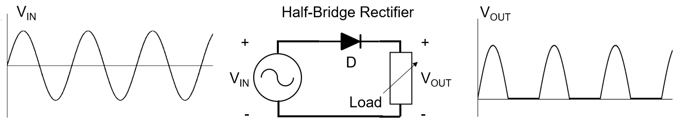
After rectification, the resulting sine wave will have low mean power and will not be able to power devices efficiently. A much more efficient method would be to change the negative half-wave’s polarity and make it positive. This method is called full-wave rectification, and it only requires four diodes in a bridge configuration. This arrangement maintains a stable current flow direction, regardless of the input voltage polarity.

A fully rectified wave has a higher mean output voltage than the one produced by the half-bridge rectifier, but it is still very far from being the constant DC waveform needed for powering electronic devices. Although this is a DC wave, using it to power a device would be inefficient due to the shape of the voltage wave, which changes value very quickly and very often. This periodic change in DC voltage is called a ripple — reducing or eliminating ripple is crucial to an efficient power supply. The simplest and most commonly used method for ripple reduction is the use of a large capacitor at the rectifier output, called a reservoir capacitor or smoothing filter. The capacitor stores voltage during the wave’s peak, then supplies the load with current until its voltage is smaller than the now-rising rectified voltage wave. The resulting waveform is much closer to the desired shape, and can be considered a DC voltage with no AC component. This final voltage waveform can now be used to power DC devices.

Passive rectification uses semiconductor diodes as uncontrolled switches, and is the simplest method to rectify an AC wave, but it is not the most efficient.
Diodes are relatively efficient switches; they can switch on and off quickly with minimal power loss. The only problem with semiconductor diodes is that they have a forward bias voltage drop of 0.5V to 1V, which reduces efficiency.
Active rectification replaces diodes with controlled switches, such as MOSFETs or BJT transistors. The advantages of this are two-fold: First, transistor-based rectifiers eliminate the fixed 0.5V to 1V voltage drop associated with semiconductor diodes, because their resistances can be made arbitrarily small, and consequently have a small voltage drop. Second, transistors are controlled switches, which means the switching frequency can be controlled and therefore optimized.
The downside is that active rectifiers require more complicated control circuits to achieve their purpose, which requires additional components and consequently makes them more expensive.

Power Factor Correction (PFC) The second stage in a switching power supply design is power factor correction (PFC). PFC circuits have little to do with the actual conversion of AC power to DC power, but are a critical component of most commercial power supplies.
If you observe the current waveform of the rectifier’s reservoir capacitor, you’ll see that the charging current flows through the capacitor during a very short time span, specifically from the point where the voltage at the input of the capacitor is greater than the capacitor’s charge to the rectified signal’s peak. This generates a series of short current spikes in the capacitor, thus creating a significant problem not just for the power supply, but for the entire power grid due to the large quantity of harmonics that these current spikes inject into the grid. Harmonics can generate distortion that may affect other power supplies and devices connected to the grid. In a switching power supply design, the goal of the power factor correction circuit is to minimize these harmonics by filtering them out. To do so, there are two options: active and passive power factor correction. Passive PFC circuits are composed of passive low-pass filters, which attempt to eliminate higher-frequency harmonics. However, power supplies, especially in high-power applications, cannot comply with international regulations on harmonic noise using only passive PFC. Instead, they must apply active power correction.
Active PFC changes the current waveform’s shape, and makes it follow the voltage. The harmonics are moved to much higher frequencies, making them easier to filter out. The most widely used circuit for these cases is a boost converter, also called a step-up converter.

Isolated vs. Non-Isolated Switching Power Supplies
Whether a PFC circuit is present or not, the final step for power conversion is to step the rectified DC voltage down to the right magnitude for the intended application. Because the input AC waveform has been rectified at the input, the DC voltage output is going to be high: If there isn’t PFC, the output DC voltage from the rectifier will be about 320V. If there is an active PFC circuit, the boost converter’s output will be a steady DC voltage of 400V or more. Both scenarios are extremely dangerous and useless for most applications that usually require significantly lower voltages.
| Isolated AC/DC Power Supplies | Non-Isolated AC/DC Power Supplies | |
| Topology | Flyback converter | Buck converter |
| Safety | Galvanic isolation offers increased user safety | Potential current leaks could cause significant harm to users or loads |
| Size and Efficiency | Transformers add size and weight | Only one inductor needed, much smaller circuit |
| Efficiency | Transformer iron and copper losses affect efficiency | A single inductor is much more efficient than an entire transformer |
| Complexity | Control circuitry is needed for both |
|
The main concern when choosing which step-down method to use is safety. The power supply is connected to the AC mains at the input, which means if there was a current leak to the output, an electric shock of this proportion could severely injure or cause death, and damage any device connected to the output. Safety can be achieved by magnetically isolating the input and output circuits of a mains-connected AC/DC power supply. The most widely used circuits in isolated AC/DC power supplies are flyback converters and resonant LLC converters, because they include galvanic or magnetic isolation.
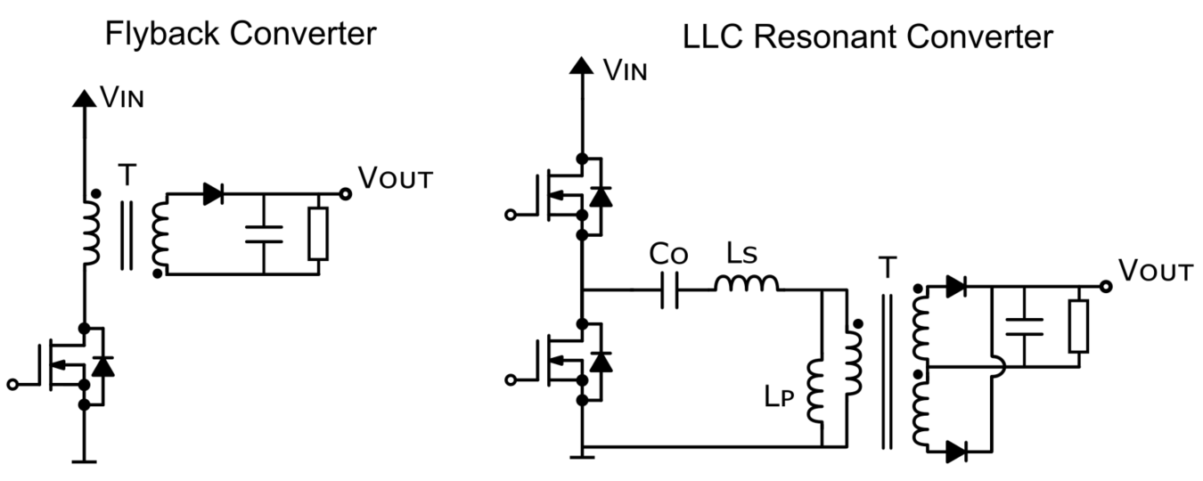
The use of a transformer means that the signal cannot be a flat DC voltage. Instead, there has to be a voltage variation, and therefore a varying current, in order to transfer the energy from one side of the transformer to the other through inductive coupling. Consequently, both flyback and LLC converters “chop” the input DC voltage into a square wave, which can be stepped down via a transformer. Then the output wave has to be rectified again before going to the output.
Flyback converters are mainly used for low-power applications. A flyback converter is an isolated buck-boost converter, which means that the output voltage can be either higher or lower than the input voltage, depending on the transformer’s turns ratio between the primary and secondary winding. The operation of a flyback converter is very similar to that of a boost converter. When the switch is closed, the primary coil is charged by the input, creating a magnetic field. When the switch is open, the charge in the primary inductor is transferred to the secondary winding, which injects a current into the circuit, powering the load. Flyback converters are relatively easy to design, and require fewer components than other converters, but are not very efficient because there are significant losses due to the hard switching from forcing the transistor to turn on and off arbitrarily. Especially in high-power applications, this is very detrimental to the transistor’s lifecycle and generates significant power losses, which is why flyback converters are better suited to low-power applications, usually up to 100W.
Resonant LLC converters are more commonly used in high-power applications. These circuits are also magnetically isolated through a transformer. LLC converters are based on the phenomenon of resonance, which is the amplification of a certain frequency when it matches a filter’s natural frequency. In this case, an LLC converter’s resonant frequency is defined by an inductor and a capacitor connected in series (LC filter) with the added effect of the transformer primary inductor (L), hence the name LLC converter.
LLC resonant converters are preferred for high-power applications because they can produce zero-current switching, also known as soft switching. This switching method turns the switch on and off when the current in the circuit approaches zero, minimizing the transistor’s switching losses, which in turn reduces EMI and improves efficiency.

As we all known one of the limitations of AC/DC power supplies are the size and weight of the input transformer, that due to the low operating frequency (50Hz) demands large inductors and magnetic cores in order to avoid saturation.
In switching power supplies, the oscillation frequency in the voltage is significantly greater (above 20kHz at the very least). This means that the step-down transformer can be smaller, because high frequency signals generate fewer magnetic losses in linear transformers. The size reduction of input transformers enables the miniaturization of the system, to the point where an entire power supply fits into a case the size of the mobile phone chargers we use today.
There are DC devices that don’t need the isolation provided by the transformer. This is commonly seen in devices that don’t need to be directly touched by the user, such as lights, sensors, IoT, and more, because any manipulation of the device’s parameters is done from a separate device, such as a mobile phone, tablet, or computer.
This offers great benefits in terms of weight, size, and performance. These converters reduce the output voltage levels using a high-voltage buck converter, also called a step-down converter. This circuit could be described as the inverse of the boost converter explained previously. In this case, when the transistor switch is closed, the current flowing through the inductor generates a voltage across the inductor that counteracts the voltage from the power source, reducing the voltage at the output. When the switch opens, the inductor releases a current that flows through the load, maintaining the voltage value at the load while the circuit is cut off from the power source.
In AC/DC switching power supplies, a high-voltage buck converter is used because the MOSFET transistor that acts as a switch must be able to withstand large changes in voltage. When the switch is closed, the voltage across the MOSFET is close to 0V; but when it opens, that voltage goes up to 400V for single-phase applications, or 800V for three-phase converters. These large, abrupt changes in voltage could easily damage a normal transistor, which is why special high-voltage MOSFETs are used.

Buck converters can be much more easily integrated than a transformer, because only one inductor is needed. They are also much more efficient at stepping down voltage, with a normal efficiency upwards of 95%. This level of efficiency is possible because transistors and diodes have almost no switching power loss, so the only loss comes from the inductor. One example of a non-isolated AC/DC power supply output regulator is the MPS MP17xA family. This family can control many different converter topologies, such as buck, boost, buck-boost or flyback. It can be used for voltages up to 700V, meaning it is intended for single-phase supplies. It also has a green mode option, where the switching frequency and peak current decrease proportionately to the load, improving the power supply’s overall efficiency. Below picture shows the typical application circuit for the MP173A, where it is regulating a buck converter, composed of an inductor (L1), diode (D1), and capacitor (C4). The resistors (R1 and R2) make a voltage divider that provides the feedback voltage (FB pin), closing the control loop.

Switching AC/DC power supplies offer increased performance for a fraction of the size, which is what has made them so popular. The downside is that their circuits are significantly more complex, and they require more precise control circuits and noise cancellation filters.
Summary
AC/DC switching power supplies are currently the most efficient way of transforming AC power to DC power. The power is converted in three stages:
Input rectification: This process takes the AC mains voltage and converts it into a DC rectified wave using a diode bridge. A capacitor is added at the output of the bridge to reduce the ripple voltage.
Power factor correction (PFC): Because of the nonlinear current in the rectifier, the harmonic content of the current is quite large. There are two ways two resolve this. The first is passive PFC, using a filter to dampen the effect of the harmonics, but it is not very efficient. The second option, called active PFC, uses a switching boost converter to make the current waveform follow the input voltage shape. Active PFC is the only method of designing a power converter that meets current standards of size and efficiency.
Isolation: Switching power supplies can be isolated or non-isolated. A device is isolated when the power supply’s input and output are not physically connected. Isolation is done through the use of transformers, which galvanically isolate the two halves of the circuit. However, transformers can only transfer electric power when there is a variation in current, so the rectified DC voltage is choped up into a high-frequency square wave, which is then transferred to the secondary circuit, where it is rectified again and finally transmitted to the output.
There are many different aspects to consider when designing a switching power supply, especially related to safety, performance, size, termperature, EMI,weight, etc.